Bump and Tape sensors done
Today and yesterday we worked on getting our bump and tape sensors to work and started to integrate them with the rest of the robot. Here's a list of what we done:
- I worked on the bump module code to make sure the sensors are detected properly. While debugging the perfboard, I found that when unbumped the sensor ports return 3.3 volts which is convienent. However, the Uno32 does not detect the first bump sensor even though its LED indicator responds correctly. It turns out that this IO connection is not soldered in the perfboard. Otherwise, I verified that all the sensors and LEDs function correctly.
- Luis and I worked on bump sensor placement. We drilled holes on our MDF board to place our sensors which could be triggered when the bumper gets hit both in front and in the left and right sides.
- Jake started to work on the perfboard track wire sensors.
- I also started to look over the tape sensor module code Luis started. Later that night Aaron helped write the code for detecting the tape sensors.
The next day:
- We determined the distances of the by experimenting with the sensors to determine possible threshold values. The threshold values are based on a precondition that the tape sensor is facing normal to the surface while half an inch away. We finalized the tape sensor code and decided to work on the hystersis later. We found that in general the upper bound for all five sensors is slightly more than 550, this is when the tape sensor is over the tape while being half an inch away, while the lower bound value is slightly lower than 530 when the tape sensor is over the white surface. We decided on an upper and lower hysteresis bound of 550 and 535. This takes into account of our observation that the tape sensor value flctunates more when over the tape than when over the white surface. Our test harness now reports all five sensors detecting the black tape when we test this.
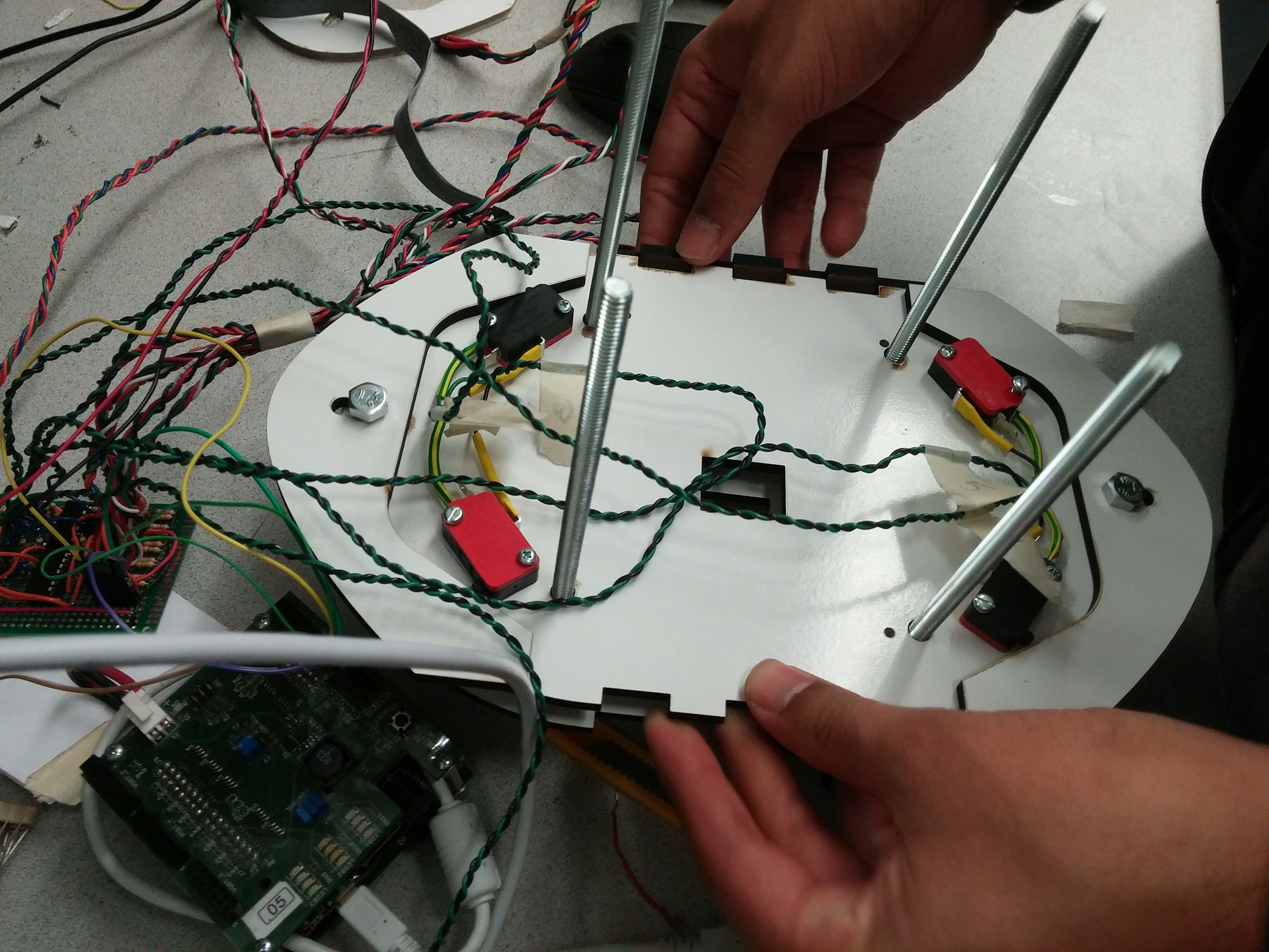
- Luis reviewed our bump sensor placement and realized some of our drilled holes were not placed very well. We looked into different bump sensor locations, but ultimately Luis figured out that if the nail polish strips we were using to act as the lever portion for the bump switch, then they could be reposition to be next to the bumper sensor. When screwed in, the bump sensors would trigger to a collision, but we gained some needed space on our cramped bases! Here is a picture of this:
- We looked into tape sensor placement and realized there is very little space to put a base under the motor hold boxes for the tape sensors. We decided to cut a new base for our sensors in foamcore to prototype. We are now currently modeling a smaller version of th motor box along with tab slots to secure a mounted base with holes for our tape sensors.
- Jake continued soldering the two track wire sensors on one perfboard and reports that he has amplified the signal so that it has a range of a few inches.
Written on November 18, 2015